Add non Skydive nodes in topology
by Masco Kaliyamoorthy, 27/11/2018Skydive displays the network topology by receiving the network events from the skydive agents. You ever wondered how to add or display in topology diagram, a network components which is out of the skydives’ agent network or a non network entities like TOR, data store and etc. No more worries on that, thanks to the skydive ‘Topology Rules’ API.
Since version 0.20, Skydive provides Topology Rules API, can be used to create new nodes and edges and update existing nodes’ metadata. Topology Rules API divided in two APIs, node rule API and edge rule API. Node rule API is used for create a new node and update metadata of existing node. Edge rule API is used for create edge between two nodes i.e linking two nodes.
In this blog we will see two use cases, one is a network component which is not part of skydive network. Secondly, a non network component.
Before that, we will see some basic usage of Topology rules API.
Create Node
To create node, You must provide a unique node name and a valid node type. You can provide some optional params as well.
skydive client node-rule create --action="create" --node-name="node1" --node-type="fabric" --name="node rule1"
{
  "UUID": "ea21c30f-cfaa-4f2d-693d-95159acb71ed",
  "Name": "node rule1",
  "Description": "",
  "Metadata": {
    "Name": "node1",
    "Type": "fabric"
  },
  "Action": "create",
  "Query": ""
}
Update Nodes’ Metadata
To update the metadata of an existing node, you must provide a ‘gremlin query’ to chose the nodes you want to update the metadata. According to your query you can update the metadata of one or more nodes with single node rule.
skydive client node-rule create --action="update" --name="update rule" --query="G.V().Has('Name', 'node1')" --metadata="key1=val1, key2=val2"
{
  "UUID": "3e6c0e15-a863-4583-6345-715053ac47ce",
  "Name": "update rule",
  "Description": "",
  "Metadata": {
    "key1": "val1",
    "key2": "val2"
  },
  "Action": "update",
  "Query": "G.V().Has('Name', 'node1')"
}
Create Edge
To create an edge, you should provide the source and destination nodes AND relation type of the edge, to create a child node the value of relation type should be ownership similarly to create a layer2 type link the value of relation type should be layer2. You can create more than one link between two nodes but the relation type should be different.
skydive client edge-rule create --name="edge" --src="G.v().has('TID', '2f6f9b99-82ef-5507-76b6-cbab28bda9cb')" --dst="G.V().Has('TID', 'd6ec6e2f-362e-51e5-4bb5-6ade37c2ca5c')" --relationtype="both"
{
  "UUID": "50fec124-c6d0-40c7-42a3-2ed8d5fbd410",
  "Name": "edge",
  "Description": "",
  "Src": "G.v().has('TID', '2f6f9b99-82ef-5507-76b6-cbab28bda9cb')",
  "Dst": "G.V().Has('TID', 'd6ec6e2f-362e-51e5-4bb5-6ade37c2ca5c')",
  "Metadata": {
    "RelationType": "both"
  }
}
First use case
In this use case we will look how to show a non network device in skydive topology. Let’s consider we have a datastore that needs to be displayed in skydive topology diagram with some useful metadata.
We just need to create a Node rule to add the device in the topology. We can add the metadata of the device as part of the create command or can create one or more update node rule command later.
Run the below Node rule command to add the storage device in the topology diagram.
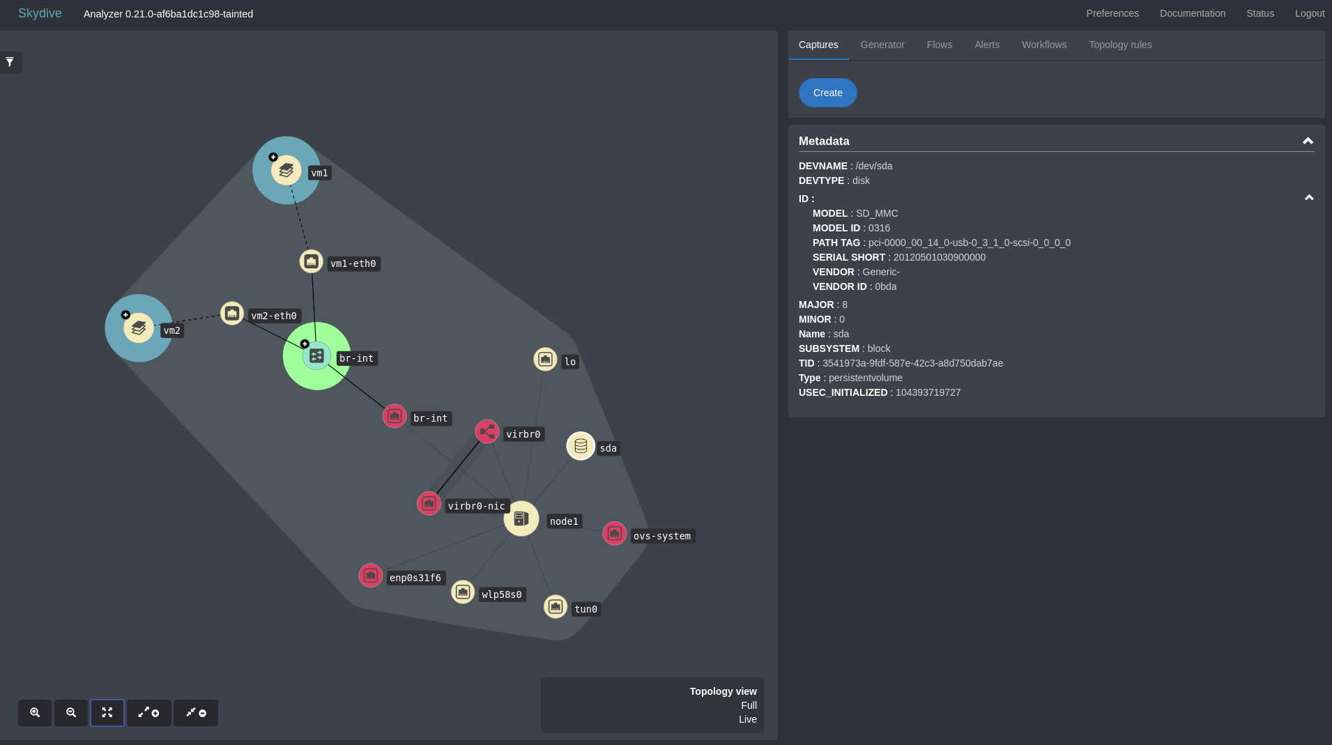
skydive client node-rule create --action="create" --node-name="sda" --node-type="persistentvolume" --metadata="DEVNAME=/dev/sda,DEVTYPE=disk,ID.MODEL=SD_MMC, ID.MODEL ID=0316, ID.PATH TAG=pci-0000_00_14_0-usb-0_3_1_0-scsi-0_0_0_0, ID.SERIAL SHORT=20120501030900000, ID.VENDOR=Generic-, ID.VENDOR ID=0bda, MAJOR=8, MINOR=0, SUBSYSTEM=block, USEC_INITIALIZED=104393719727"Run the below Edge rule command to link the created node with the host node
skydive client edge-rule create --src="G.V().Has('Name', 'node1')" --dst="G.V().Has('Name', 'sda')" --relationtype="ownership"After the above commands now you can see the device visible in the skydive topology diagram with the given metadata as shown in the below image.
Second use case
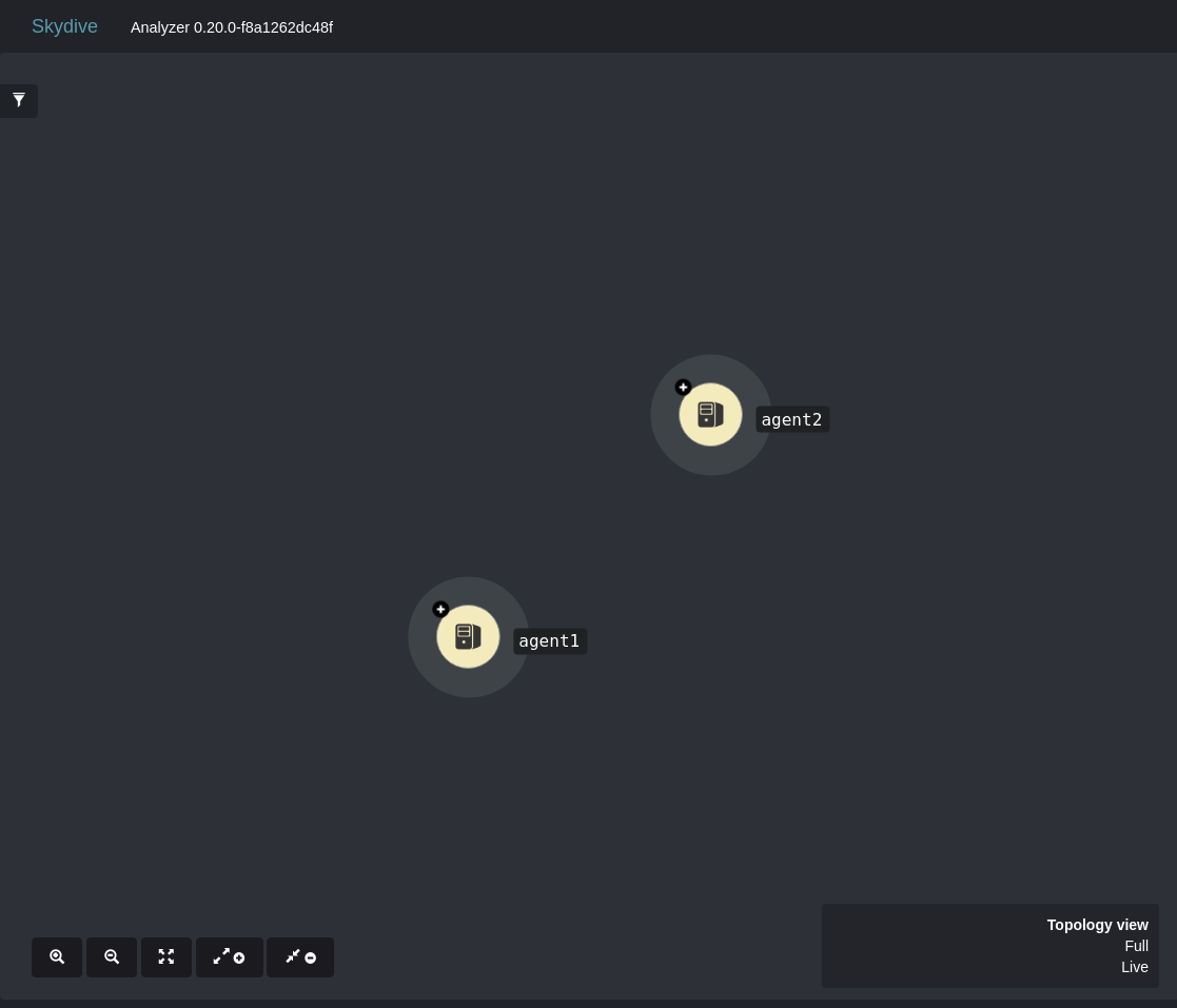
In this use case, we will see how to add a network device which is not part of the skydive network. Let’s consider this example, we have two skydive agents running in two different hosts, to connect those two hosts we need a TOR switch. Even Though we can achieve this via defining a fabric nodes and links in config file, let’s see how we can do the same using Topology rules API.
Without TOR switch, two agents will look like two different node without any links as shown in the below image.
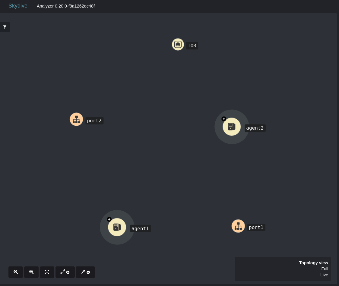
Now run the below Node Rule commands to create a TOR switch and Ports.
skydive client node-rule create --node-name="TOR" --node-type="fabric" --action="create"
skydive client node-rule create --node-name="port1" --node-type="port" --action="create"
skydive client node-rule create --node-name="port2" --node-type="port" --action="create"
You can see, the TOR switch and ports are created and added to the skydive topology and now the topology will look like as shown in the below image.
Now run the below Edge Rule commands to create a links between the TOR switch, port1 and the public interface of the host1.
skydive client edge-rule create --src="G.V().Has('Name', 'TOR')" --dst="G.V().Has('Name', 'port1')" --relationtype="ownership"
skydive client edge-rule create --src="G.V().Has('Name', 'TOR')" --dst="G.V().Has('Name', 'port1')" --relationtype="layer2"
skydive client edge-rule create --src="G.V().Has('TID', '372c254d-bac9-50c2-4ca9-86dcc6ce8a57')" --dst="G.V().Has('Name', 'port1')" --relationtype="layer2"
Run the below commands to create a links between the TOR switch, port2 and the public interface of the host2
skydive client edge-rule create --src="G.V().Has('Name', 'TOR')" --dst="G.V().Has('Name', 'port2')" --relationtype="layer2"
skydive client edge-rule create --src="G.V().Has('Name', 'TOR')" --dst="G.V().Has('Name', 'port2')" --relationtype="ownership"
skydive client edge-rule create --src="G.V().Has('TID', '50037073-7862-5234-4996-e58cc067c69c')" --dst="G.V().Has('Name', 'port2')" --relationtype="layer2"
Now the ownership and layer2 links between the TOR switch and port AND layer2 links between the agents and ports are created. Now the final topology will look like as shown in the below image.
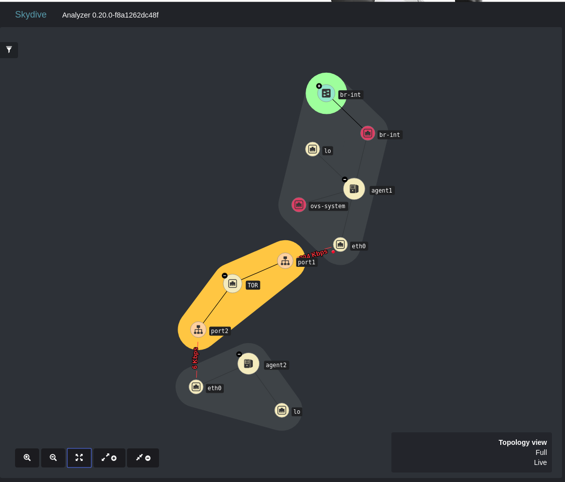
Now the two hosts/agents linked properly and you can check the connectivity or create a shortest path capture between the two hosts.